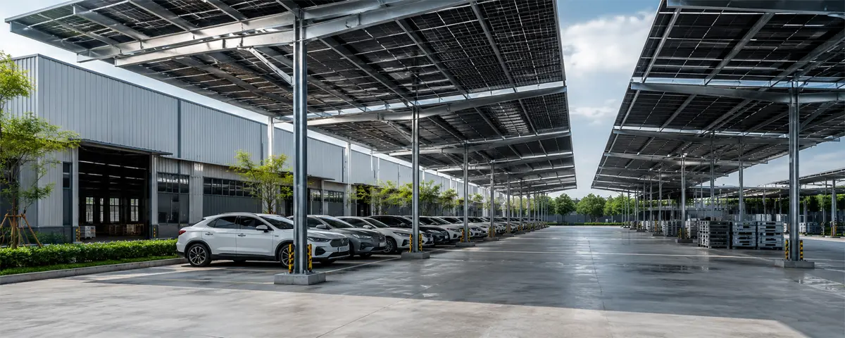



Solar Carport Mounting Systems India 2026: How to Turn Parking Lots into Solar Power Plants — Complete Guide
22/05/2026
SECI, PSPCL & State DISCOM Solar Tenders May 2026: Upcoming Projects & Mounting ProcurOuement tlook
26/05/2026
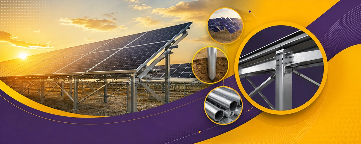
Why Getting the Structure Right Is Everything in Solar
You can have the best solar panels on the market, a solid EPC partner, and a favorable land deal — and still watch your project underperform if the mounting structure isn't engineered for the site. It sounds basic, but it's one of the most overlooked parts of utility-scale solar planning.
For developers working on projects across India and the GCC (Gulf Cooperation Council) region, the challenge is compounded by dramatically different wind speeds, soil conditions, corrosion environments, and regulatory expectations. A 10 MW plant in Rajasthan faces completely different structural demands than a 50 MW plant in Saudi Arabia or the UAE.
That's exactly where a solar mounting structure load calculator becomes indispensable. It's not just a spreadsheet — it's the foundation for your entire civil and structural design strategy.
What a Solar Mounting Structure Load Calculator Actually Does
At its core, a load calculator for solar mounting systems helps engineers and project developers determine:
- Dead loads — the self-weight of the structure and panels
- Wind loads — based on regional wind zone classifications
- Seismic loads — especially relevant for parts of India and the Middle East
- Snow loads — applicable in higher-altitude Indian projects
- Soil bearing capacity and pile embedment depth — to ensure the foundations won't shift over the project's 25-year life
A well-built calculator inputs your project's MW capacity, panel configuration, tilt angle, row spacing, and site-specific environmental data, then outputs structural weight estimates, pile sizes, and material specs — ready for procurement and detailed engineering.
For MW-scale projects, even a marginal error in these estimates can mean tonnes of excess steel or, worse, under-designed foundations that fail during a dust storm or cyclone.
MW-wise Weight Estimates: What to Expect
One of the most frequent questions from developers is: "How much steel do I actually need?" The answer varies depending on structure type — fixed-tilt vs. single-axis tracker — but here are realistic benchmarks:
Fixed-Tilt Ground Mount Systems:
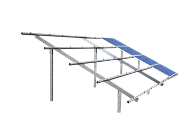
- 1 MW: Approximately 40–60 MT of galvanized steel (depending on wind zone and panel size)
- 5 MW: 200–300 MT
- 10 MW: 400–600 MT
- 50 MW: 2,000–3,000 MT
Single-Axis Trackers (SAT): Trackers are mechanically more complex and typically add 15–25% more steel weight per MW compared to fixed-tilt, but their energy yield advantage (12–18% more generation) usually justifies the cost in high-irradiance zones like Rajasthan, Gujarat, or the Arabian Peninsula.
The load calculator accounts for purlin spacing, post height, table width, and the number of module rows per table — all of which directly affect the steel tonnage and, consequently, your BOM (Bill of Materials) cost.
Pile Depth Specifications: India vs. GCC
Pile depth is where site-specific geology becomes critical. Driving piles too shallow risks structural failure; going too deep inflates civil costs unnecessarily.
India
India's diverse soil landscape makes generalization risky. Here's a practical breakdown by region:
- Sandy/Alluvial soils (Rajasthan, Gujarat plains): Pile embedment of 1.5–2.2 m is typical for MS/GI piles in fixed-tilt systems
- Black cotton/expansive soils (Maharashtra, Telangana): Requires deeper embedment of 2.0–2.8 m or precast concrete pedestals due to swell-shrink behavior
- Rocky terrain (Andhra Pradesh, Karnataka Deccan plateau): Anchor bolts or rock socket piles; embedment can be reduced to 0.8–1.2 m with proper grouting
- Coastal zones (Tamil Nadu, Odisha): Corrosion-resistant coatings and deeper embedment to counter saline soil conditions
Wind zones in India (as per IS 875 Part 3) significantly impact pile sizing. Zone V areas — which include coastal belts and the Andaman Islands — demand structures designed for wind speeds up to 50 m/s.
GCC Region
The GCC presents its own set of challenges, with sandy desert soils dominating most project sites:
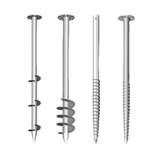
- UAE and Saudi Arabia (desert sand): Embedment depths of 1.8–2.5 m for helical or H-pile systems; pull-out testing is mandatory on most utility projects
- Oman (mountainous/rocky regions): Rock anchor solutions with 0.6–1.0 m embedment
- Qatar and Kuwait (sabkha/salt flats): Highly corrosive environments — pile depth often 2.0–3.0 m, with additional corrosion protection mandated
The GCC also sees extreme wind events and sandstorms, so structures are typically designed to IEC 61400 wind standards or ASCE 7, often exceeding Indian IS standards in wind load intensity.
A quality solar mounting structure load calculator integrates soil classification, pile type, and regional wind standards automatically, giving your civil team a defensible engineering basis from day one.
Galvanizing Specifications: Getting the Corrosion Protection Right
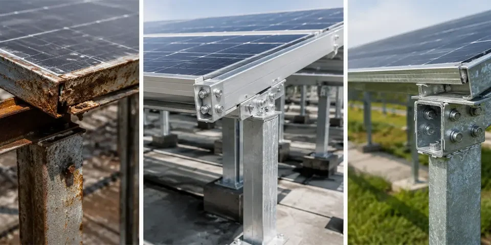
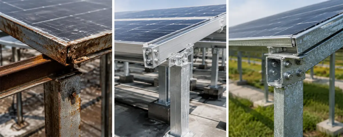
Galvanizing is often treated as a checkbox — it's not. Selecting the wrong coating thickness or process is one of the fastest ways to see your mounting structure degrade years before the panels do.
Standard Hot-Dip Galvanizing (HDG) Specs
For most ground-mount solar projects, hot-dip galvanizing to IS 2629 (India) or ISO 1461 (GCC/International) is the baseline requirement.
Typical coating thickness guidelines:
| Application | Minimum Coating (µm) | Typical Spec |
|---|---|---|
| Structural members (purlins, rafters) | 85 µm | IS 2629 / ISO 1461 |
| Piles / foundation posts | 100–120 µm | For buried sections |
| Fasteners & bolts | 45–55 µm | ISO 10684 (mechanically galvanized) |
| Coastal / sabkha zones | 140+ µm | Enhanced corrosion protection |
Pre-Galvanized vs. Hot-Dip: Which to Choose?
Pre-galvanized (mill-galvanized) steel is cheaper and faster to fabricate but offers lower coating thickness (typically 20–40 µm), making it suitable only for non-aggressive inland environments. For anything near the coast, desert saline soil, or high-humidity zones, post-fabrication hot-dip galvanizing is non-negotiable.
In the GCC, many utility project specifications also require additional epoxy or polyurethane topcoats on pile sections that will be below the soil line — particularly in sabkha regions of Qatar and UAE where chloride concentrations are extremely high.
Market Trends Driving Demand for Better Structural Engineering
The solar mounting systems market in India and GCC is scaling faster than most infrastructure sectors. India is targeting 500 GW of renewable energy by 2030, with utility-scale solar making up the lion's share. The GCC collectively has announced projects totaling over 100 GW through the late 2030s — including Saudi Arabia's NEOM, the UAE's Al Dhafra expansion, and Oman's Manah Solar project.
This pipeline is creating intense pressure on developers to be faster, more cost-accurate, and less reliant on conservative engineering assumptions that inflate CAPEX. MW-wise structural calculators are becoming standard tools in the pre-FEED (Front-End Engineering Design) stage.
Other trends shaping the space:
- Bifacial panel adoption is pushing structures to optimize height and row spacing — affecting load calculations significantly
- Agrivoltaic projects are increasing ground clearance requirements, demanding re-engineered pile and post specifications
- Floating solar introduces entirely new structural load considerations beyond the scope of conventional ground-mount calculators
- Digital twin integration — leading EPCs now feed load calculator outputs directly into BIM models for real-time design iteration
Future Outlook: Smarter Structures, Lower LCOE
The next generation of solar mounting structure design tools will move beyond static load calculations. AI-assisted structural optimization, real-time soil data integration via drone-based geotechnical surveys, and automated BOM generation linked to live steel pricing are already emerging in developed markets — and are beginning to reach Indian and GCC project pipelines.
For developers, the bottom line is this: accurate structural planning at the pre-bid stage doesn't just reduce engineering risk — it directly compresses your LCOE (Levelized Cost of Energy). Every tonne of steel optimized out of your BOM, every pile that's correctly sized on the first pass, and every galvanizing spec that matches actual site conditions rather than a generic standard translates to real savings at scale.
Conclusion: Engineer the Foundation, Not Just the Panels
The solar industry has matured to the point where panel efficiency gains are incremental. The next competitive frontier is engineering precision — and the solar mounting structure load calculator is one of the most practical tools available to developers and EPCs working in India and the GCC.
Whether you're planning a 1 MW rooftop-adjacent ground mount in Maharashtra or a 200 MW utility plant in Saudi Arabia, getting your MW-wise weight estimates, pile depths, and galvanizing specs right from the start isn't just good engineering — it's good business.
If you're evaluating PV racking solutions for your next project, start with the structure. Everything else sits on top of it.